For large facilities needing 1 MW-class capacity and complete system interfaces
Can integrate with ATS, LV distribution, paralleling, day tanks and remote monitoring to serve multiple critical feeders or operate as one unit in a multi-set system.
Typical Project Configuration · Customizable Range · 1000kW
This 1 MW-class containerized generator serves large factories, hospitals, data-center auxiliaries and commercial complexes. Load recovery, redundancy, LV or MV output, thermal management and fuel autonomy are designed as one system.
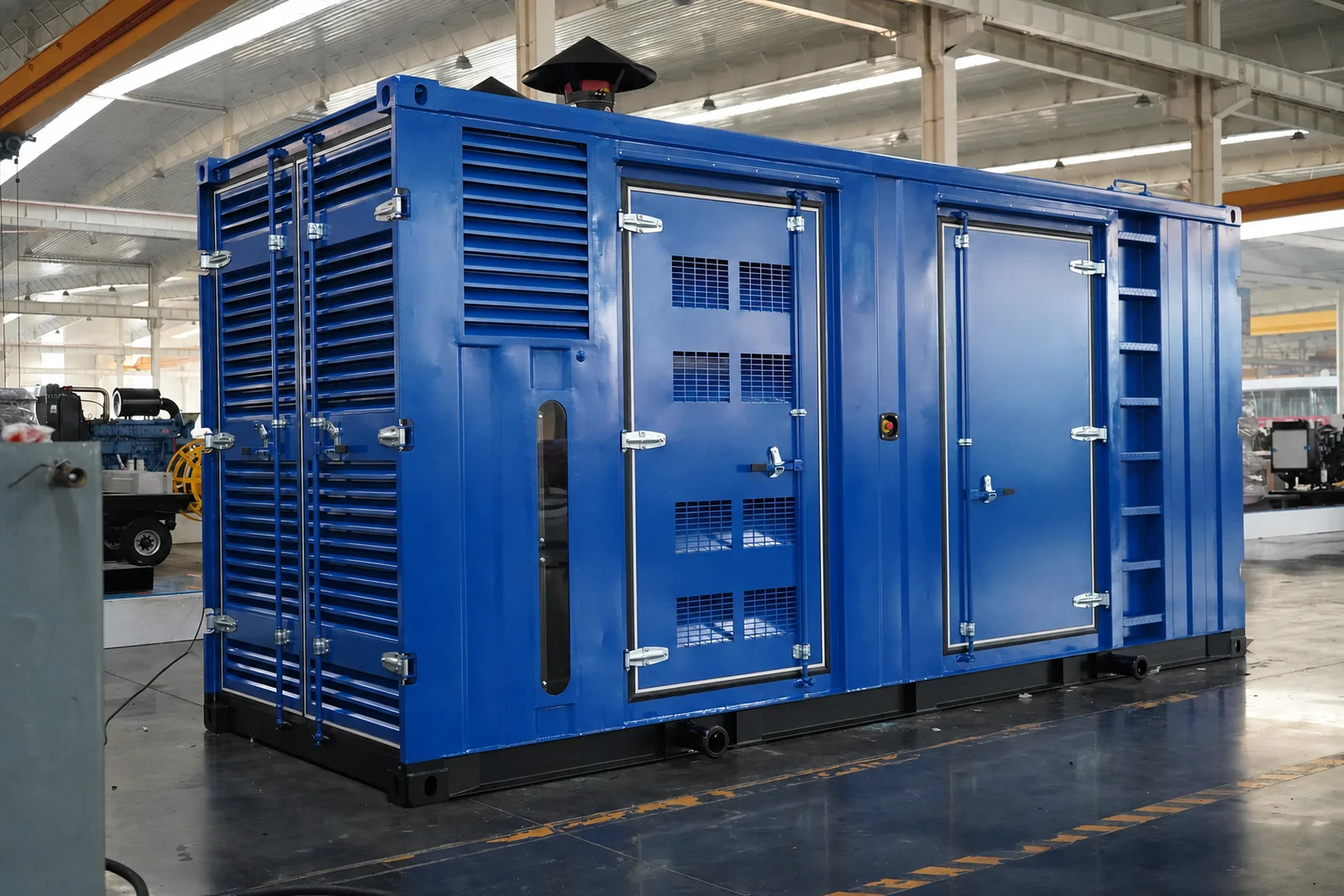
Product photos · Typical configuration
Reference 1000 kW Cummins containerized generator covering large-facility use, alternator and control options, cooling, exhaust, transport and FAT/SAT boundaries.
This page presents one typical project configuration to explain output, brand combination, package format and system interfaces. The same range covers additional outputs and options; the final engine model, rating, voltage, controller, tank, dimensions and supply scope are defined for the project.
Applications
Can integrate with ATS, LV distribution, paralleling, day tanks and remote monitoring to serve multiple critical feeders or operate as one unit in a multi-set system.
Critical facilities still need an N+1 strategy, bus architecture, protection coordination, load zoning and maintenance windows—not only more single-unit capacity.
Core configuration
The engine and radiator are matched to output, duty and ambient temperature, with attention to load response, service access and local support.
The alternator is selected for load characteristics, excitation, insulation and temperature rise; PMG can be specified for demanding motors or UPS loads.
The controller can integrate ATS, paralleling and remote communications together with breaker, emergency stop, charging and protection functions.
The base, mounts, grounding, cable exit and lifting interfaces form the package structure; container versions also integrate airflow, exhaust, weatherproof doors and service space.
Key parameters
These are the parameters that shape selection and interfaces. Fuel consumption, noise and dimensions are supplied after the engine model, load factor and site environment are defined.
| Reference output | 1000 kW / 1250 kVA @ PF 0.8 |
|---|---|
| Rating basis | Prime/standby rating confirmed against the final engine model, ISO 8528 conditions and project duty |
| Frequency / speed | 50 Hz / 1500 rpm or 60 Hz / 1800 rpm |
| Rated voltage | 380 / 400 / 415 / 440 / 480 V; other voltages by project |
| Phase / power factor | Three-phase, four-wire; reference PF 0.8 |
| Control system | DSE / ComAp / SmartGen selected for ATS, paralleling and communications |
| Cooling and environment | Container airflow, resistance and 40°C/50°C ambient capability verified by heat balance |
| Fuel autonomy | Base tank, day tank or bulk storage sized from target runtime and usable fuel volume |
Quality and delivery
Engine, alternator, controller and breaker brands, models and serial information are listed in the technical and delivery documents.
Base steel, welds, fasteners, mounts and coating are included in manufacturing inspection; container packages also cover doors, hinges, locks, seals and lifting points.
Radiator, airflow, wiring terminations, grounding, protection and safety separation support loaded stability and long-term serviceability.
Factory records can cover starting, no-load and staged-load operation, voltage, frequency, alarms and protection, with witnessed FAT available by project.
Project configuration
Provide the country and city, load list, frequency, voltage, duty, installation environment and required delivery. A HOHANK engineer will verify output, component selection, interfaces and the supply boundary.