Standby equipment rarely runs and cannot be watched continuously
Battery voltage, charger supply, automatic mode and periodic test records expose risks that develop while the generator is idle.
Power-System Component / Operational Visibility and Maintenance Closure
Remote monitoring is not another screen. Its value is to make generator, ATS, distribution, fuel and environmental conditions visible early, describe abnormalities accurately and preserve the response record, reducing outage risk at unattended and multi-site facilities.
Why Add Remote Monitoring
Remote monitoring does not replace site personnel. It helps teams detect abnormalities earlier, shorten fault diagnosis, preserve test and maintenance evidence and manage multiple locations under the same rules.
Battery voltage, charger supply, automatic mode and periodic test records expose risks that develop while the generator is idle.
Generator, ATS, fuel, alarm and maintenance status can be organized so regional teams see priorities rather than isolated messages.
Uploading data without alarm levels, recipients and response rules does not shorten recovery time.
Leaks, abnormal noise, loose connections, corrosion and blocked ventilation still require site checks; remote data adds evidence rather than replacing them.
Complete Data Path from Equipment to Responsible Person
The system should answer where data originates, how it travels, who receives it, what action follows and how closure is recorded. A missing stage leaves alarms sitting on a screen.
Collect voltage, current, frequency, power, speed, oil pressure, coolant temperature, battery, fuel level and switch positions.
Record starts, stops, automatic mode, protective actions and fault codes with a reliable event sequence.
Select Modbus, Ethernet, cellular or another compatible path around controller protocol and site distance.
Organize status by site, device and severity while retaining run hours, events and maintenance records.
Use platform, email, SMS or other channels by severity instead of sending every alarm to everyone.
Record diagnosis, site action, replaced parts and recovery testing as traceable maintenance evidence.
Product and System Configurations
Do not begin with one fixed platform. First confirm controller compatibility, essential data, network conditions, alarm ownership and maintenance workflow, then define hardware and service boundaries.
Shows electrical, engine and alarm parameters at the generator for single-site projects with regular local inspection.
Uploads one generator or a small group to a remote endpoint with basic alarms, trends and run-hour records.
Combines source transfer, switch positions, fuel level, temperature, water leakage and other critical points into one standby-power view.
Standardizes sites, alarm levels, permissions, maintenance plans and response records across cities, campuses or facility portfolios.
Remote start, stop, reset or control is enabled only where site safety, control logic, authorization and local management rules permit it. Monitoring, alarms and records should normally come before remote control.
Data Groups and Alarm Levels
More data does not automatically create a better system. Basic status, critical faults, developing trends and maintenance milestones should be separated so noise does not hide events that threaten power continuity.
Controller, Gateway and Monitoring Interfaces
Customers do not need to learn communications protocols, but they should verify the controller model, readable data points, gateway interface, offline buffering, permissions and alarm tests before the platform goes live.
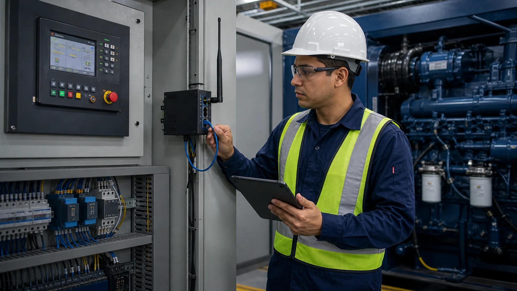
Compatible DSE, HGM or other controllers provide operating data, protection alarms and event history.
Confirm RS485, Modbus or other interfaces, register addresses, read/write permissions and engineering units.
Converts and uploads field data over wired Ethernet, cellular service or another project-defined path.
Gateways, routers and essential sensors need stable power so monitoring does not disappear during the outage.
Fuel level, temperature, humidity, water leakage, vibration or access points are added by risk rather than by quantity.
Verify room shielding, signal strength, antenna location, data allowance and local carrier coverage.
Separate viewing, acknowledgment, maintenance and control permissions and retain authorization and audit logs.
Store critical events during a network interruption and upload them after recovery so the fault sequence remains complete.
Six Project Inputs
Provide generator, ATS, paralleling, distribution, tank and sensor models, quantities and available communications interfaces.
Separate real-time status, protection alarms, trends, maintenance hours and items that still require site inspection.
Confirm Ethernet, cellular signal, antenna location, IP rules, gateway power, outage behavior and local data service.
Define who receives each alarm, acknowledgment time, escalation timing and nighttime or holiday coverage.
Assign sites and actions by role and define account, password, log and personnel-change procedures.
Include alarm acknowledgment, site photos, actions, parts replacement, retesting and closure status.
Typical Monitoring Tasks
Hospitals and data centers connect generator, ATS, UPS auxiliaries, fuel and environmental status with drill and maintenance records.
Hotels, malls and schools standardize alarm levels, maintenance intervals and fault-reporting formats to reduce repeated clarification.
Factories, campuses and remote sites use loading, temperature, vibration, fuel and repeat-alarm trends to target site visits.
Share controller and equipment models, site count, required data, network conditions, alarm recipients, permission boundaries and maintenance workflow. HOHANK engineers will define gateways, point lists, platform functions, alarms and test scope.