If remote communications are already available
The controller, a 4G or Ethernet gateway, or the monitoring platform can provide operating status, alarms and runtime for periodic trend review.
Generator remote diagnostics and maintenance
For hospitals, shopping centers, factories, hotels, educational facilities and data centers, an engineer combines controller data, ATS records, distribution status, runtime, load changes, alarms and site evidence to identify risks before an outage.
Monitoring equipment and data points
Preventive maintenance is more than installing a camera. It connects the controller, ATS, distribution, fuel, site conditions and engineering review.
The controller, a 4G or Ethernet gateway, or the monitoring platform can provide operating status, alarms and runtime for periodic trend review.
The site team can collect controller screenshots, switchboard photographs, ATS status, videos and service records to build a traceable history.
| Category | Data collected | Application and engineering value |
|---|---|---|
 Basic remote data package Basic remote data package | Runtime, oil pressure, coolant temperature, rpm, voltage, frequency, load percentage and alarm codes |
|
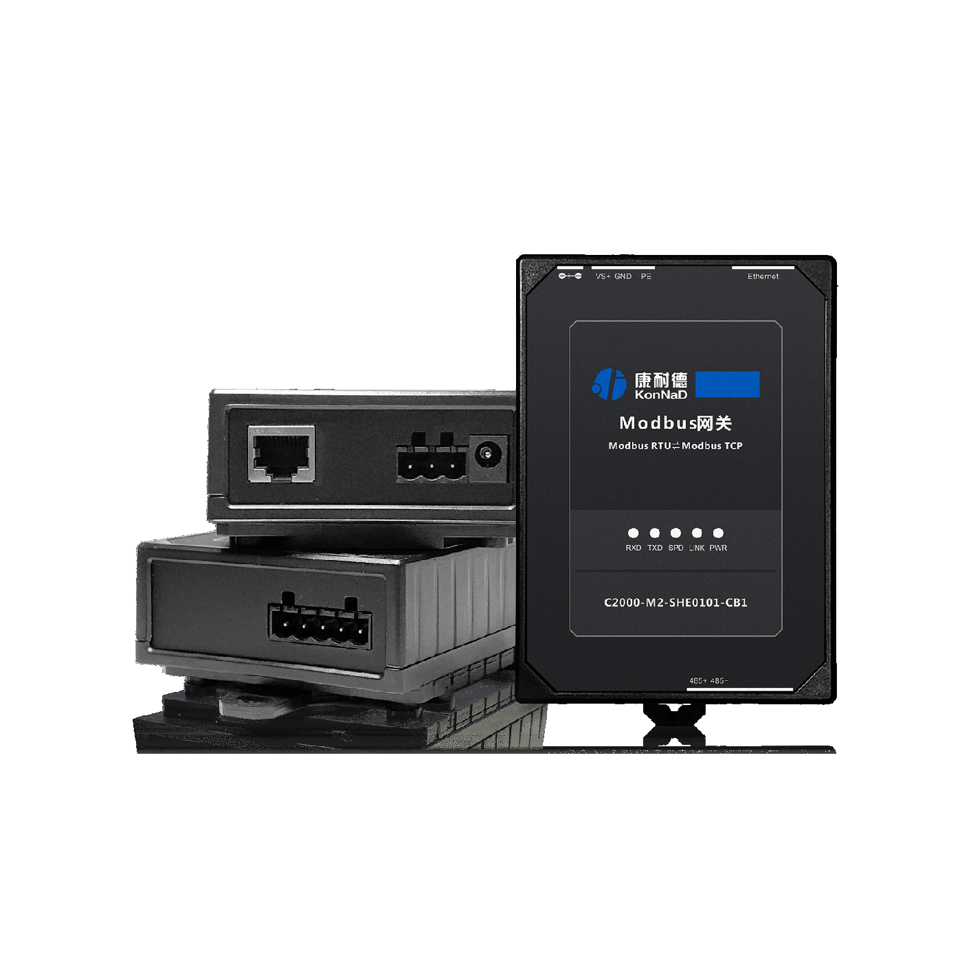 ATS and distribution monitoring package ATS and distribution monitoring package | Transfer status, utility and standby state, three-phase voltage and current, trip position and protection records |
|
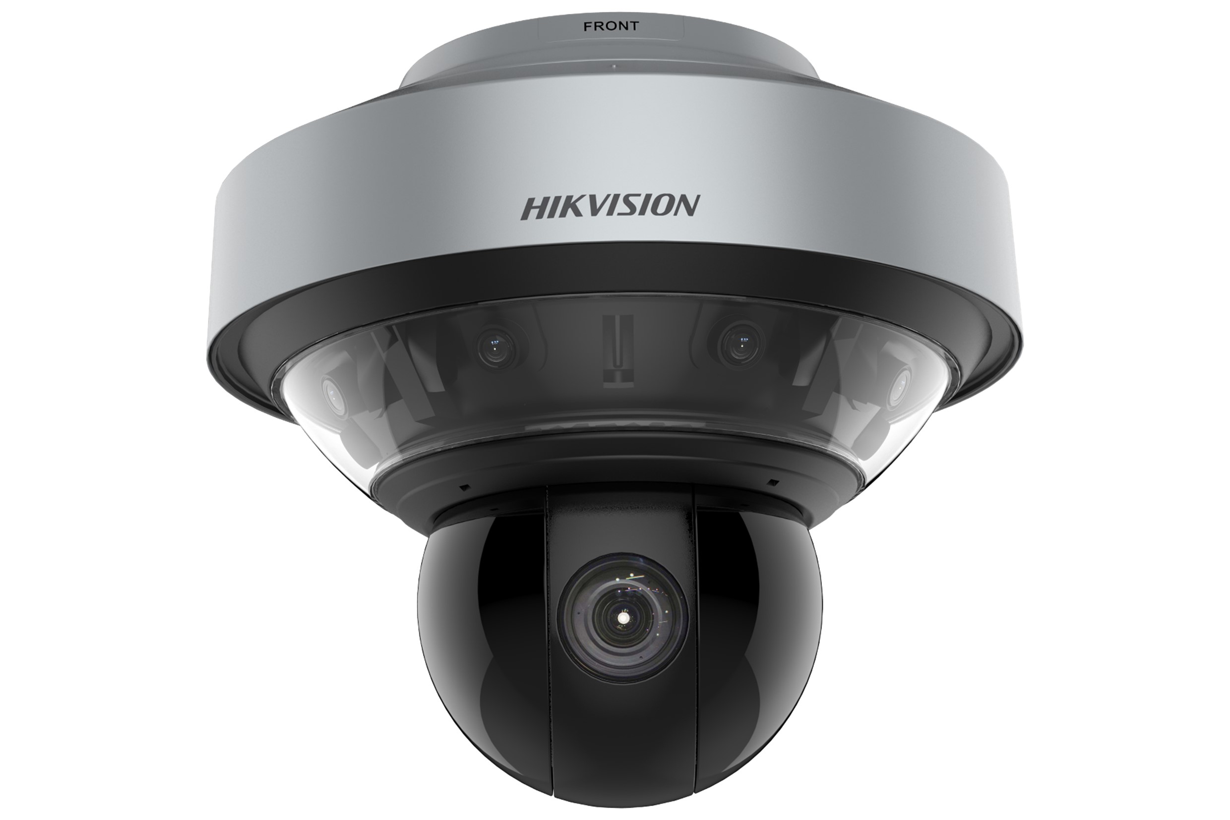 Video and thermal-imaging package Video and thermal-imaging package | Site video, personnel entry, exhaust condition, leaks and abnormal switchboard heating |
|
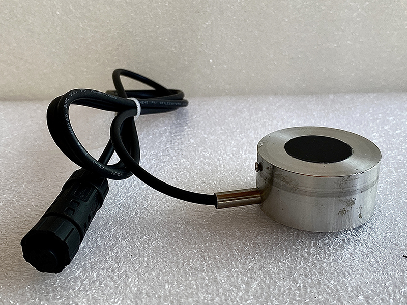 Fuel and refueling package Fuel and refueling package | Fuel level, daily consumption, refueling time, low-level alarms and abnormal consumption trends |
|
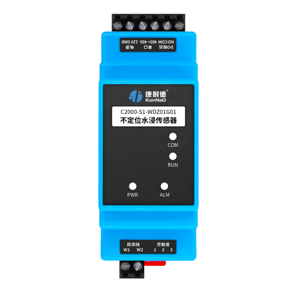 Plant-room environmental safety package Plant-room environmental safety package | Temperature, humidity, water ingress, smoke, access status and monitoring-system power |
|
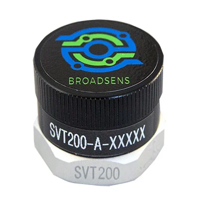 Predictive-maintenance extension Predictive-maintenance extension | Vibration trends, local hot spots, abnormal variation, recurring alarms and runtime |
|
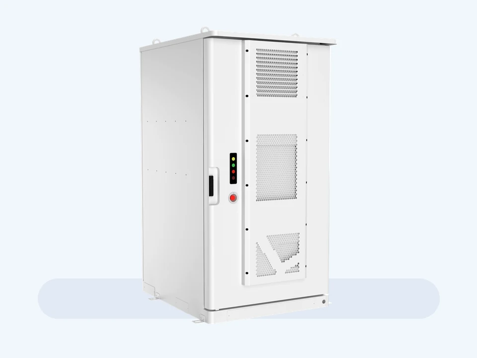 UPS, EMS and BESS extension UPS, EMS and BESS extension | SOC, SOH, charge and discharge power, temperature, alarms, fire-system status and communications |
|
UPS/EMS, BMS, PCS, SOC, power, temperature and alarm data can be reviewed to verify that the entire backup chain operates as designed.
Review Critical-Facility Backup SolutionsEngineering judgment
A high-temperature, trip or start-failure alarm does not have the same priority in an ICU, operating room, fire system, elevator, cold chain, production line, UPS or cooling system. First confirm the operating risk, then identify the technical cause.
| Data source | Key data | What it helps assess |
|---|---|---|
| Generator controller | Runtime, oil pressure, coolant temperature, rpm, voltage, frequency, load percentage and alarm codes | Helps assess generator condition, the service window, alarm priority and whether a shutdown inspection is required. |
| ATS transfer switchboard | Utility failure, generator start, load transfer, retransfer and failed-transfer records | Confirms whether standby power actually takes the critical loads, avoiding a generator that starts but never supplies the facility. |
| Low-voltage switchboard | Three-phase current and voltage, load groups, trip location, protection events and terminal heating signs | Distinguishes generator-capacity, cabling, protection-setting and load-impact issues. |
| Paralleling control system | Per-unit load, load sharing, synchronization, voltage, frequency and paralleling alarms | Checks balanced sharing and identifies units operating at sustained high or low load. |
| Fuel and maintenance records | Fuel available, daily runtime, filter changes, oil and coolant condition, and spare-parts stock | Assesses whether fuel, maintenance, spare parts or operating cost are increasing outage-recovery risk. |
| On-site inspection | Oil or coolant leaks, exhaust, unusual noise, blocked radiators, hot cables, ventilation and access conditions | Adds site conditions that remote data cannot show, making the assessment reflect actual operation. |
| UPS, EMS and BESS | SOC, SOH, charge and discharge power, temperature, alarms, fire-system status and communications | Where UPS, EMS or BESS are installed, review their data with generator load and distribution status. |
If ICUs, operating rooms, fire protection, security, elevators, cold chain, production, UPS, cooling or communications are already affected, prioritize temporary operation, transfer or load reduction.
High temperature, low oil pressure or difficult starting often point to engine, maintenance or fuel issues; voltage and frequency variation, trips and ATS failures often point to distribution, load impact or protection settings.
Rising temperature, falling oil pressure, sustained high load or recurring alarms under comparable conditions provide more evidence than a single screenshot.
When the service window is approaching, or filter, belt, battery, sensor, AVR or controller alarms increase, prepare maintenance and spare parts in advance.
Not every alarm requires an immediate visit, and the site should not troubleshoot blindly. The engineer selects remote guidance, reduced-load observation, spare-parts preparation or on-site service.
Service team
Critical facilities need people who can interpret data and site evidence and move the issue into local inspection, factory review and spare-parts confirmation.
Reviews controller data, alarms, runtime, load changes, photographs and video to establish the likely direction.
Supports on-site inspection, initial checks, installation and maintenance confirmation when needed.
Checks factory documentation for the engine, alternator, controller, ATS, paralleling or distribution configuration.
Confirms parts, alternatives and lead time from the model, serial number, photographs and symptoms.
Provides operating data, photographs, video, load changes, operating records and the permitted scope of work.
What the customer receives
The goal is for site staff, purchasing, equipment owners and engineers to work from the same data set, reducing repeated questions, delays and visits.
Organizes runtime, alarms, load, voltage, frequency, oil pressure, coolant temperature and photographs into a traceable record.
Explains whether the issue is more likely in the generator, ATS, distribution, load impact, maintenance or spare parts.
Links runtime, environment and fault frequency to service windows, common spares and higher-risk components.
Before a visit, confirms personnel, tools, spare parts, shutdown or transfer windows, site access and operating coordination.
Engineering Support
Prepare the generator model, controller photographs, alarm codes, runtime, current load, ATS or switchboard photographs, recent maintenance records and fault video. An engineer will define remote support, spare-parts preparation or an on-site visit.
An engineer will review your information and contact you.
 WhatsApp: +86 176 8575 2779