Power cannot wait for someone to arrive and switch manually
Hospitals, shopping centers, hotels, data centers and unmanned facilities need the system to take over under predefined conditions.
Power-System Component / Critical-Load Takeover
A standby generator starting does not mean critical loads have recovered. The ATS senses the utility source, issues the generator start command, verifies a stable alternate source, transfers the load and returns it after utility recovery. It determines whether power actually reaches the circuits that need it.
Why an ATS Is Needed
The value is not merely an automatic cabinet. It turns outage detection, generator start, load transfer, fault lockout and utility return into a testable and repeatable operating process.
Hospitals, shopping centers, hotels, data centers and unmanned facilities need the system to take over under predefined conditions.
Fire systems, security, pumps, UPS and controls require a clear plan for what returns first, what is delayed and what should remain disconnected.
Without defined utility incomer, busbar, critical circuits and protection boundaries, even a large ATS may transfer the wrong load.
Actual interruption also includes source-failure detection, generator starting and stabilization delays. Sensitive loads generally require a UPS across this window.
Complete Path from Outage to Recovery
Every step needs a state, delay and failure response. Timing should follow site risk rather than applying one fixed delay set to every project.
Monitor three-phase voltage and phase loss, then use a delay to distinguish an outage from a momentary disturbance.
The generator controller executes the start cycle while monitoring fail-to-start, battery, oil pressure and set alarms.
The ATS only permits transfer after the source reaches acceptable conditions and any warm-up delay has elapsed.
Mechanical and electrical interlocks prevent unintended source paralleling, while position feedback confirms the actual state.
After a return delay, the load transfers back to utility without repeated operation during a brief recovery.
The generator runs unloaded for cooldown before stopping, while events, alarms and transfer records remain available for review.
Configuration Range
An ATS may be a standalone cabinet, part of the generator control package or integrated into a low-voltage switchboard lineup. Define the connection point before selecting the enclosure format.
Utility, generator and load enter separately, allowing flexible combination with existing sets and low-voltage boards and more freedom for cable entry.
Combines generator start/stop control, source transfer and status indication for straightforward single-set projects.
Places the ATS near the set where space is limited, while cable routes, service access, protection and load-side interfaces still require review.
For large-current or multi-zone projects, coordinating incomers, bus couplers, critical busbars, selective protection and future expansion.
If maintenance without interruption or special operating modes are required, bypass, temporary-source or multi-source transfer arrangements must be defined separately. These functions should not be assumed in a standard two-source ATS.
Rated Current and Critical Parameters
ATS selection follows current and system fault conditions, not a simple conversion from generator kW to a switch model. Protection, cables and neutral treatment must be reviewed together.
Cabinet Design and Customer Value
Customers do not need to design the ATS, but they should see the main electrical areas, service clearances and test method before delivery.
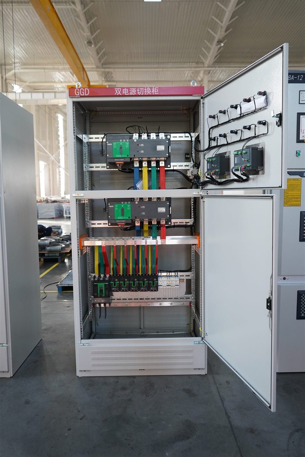
Current rating, pole count and operating life must suit load current and expected transfer frequency.
Two independent constraints prevent utility and generator from connecting together without synchronization.
Busbar section, connection torque, insulation clearances and phase identification affect temperature rise and correct cabling.
Monitors both sources and executes delays, start, transfer, return and fault-lockout logic.
Mode selection, permissions and emergency procedures should be clear to prevent unintended operation during maintenance.
Local and remote signals should distinguish utility position, generator position, fault and incomplete transfer.
Allow room for cable bending, termination, thermography, tightening and transfer-mechanism replacement.
No-load, load, source-failure, return and fault tests should create traceable records.
Six Project Inputs
Provide voltage, frequency, phases, rated current, grounding arrangement and available capacity for both sources.
List fire systems, security, pumps, elevators, UPS, controls and general loads, and identify what must transfer.
Separate millisecond, second-level and delayable loads, and confirm whether the UPS covers generator start and transfer.
Provide the existing low-voltage single-line, cable-entry direction, fault level, protection, cabinet location and service space.
Confirm delays, auto/manual modes, fire-system signals, load shedding, remote signals and fail-safe position.
Define who performs simulated outage, loaded transfer, return, alarm and maintenance tests, and how records are retained.
Typical Transfer Tasks
Hospital IT, medical equipment and data-center IT require UPS continuity; the ATS delivers stable generator power to the UPS and cooling auxiliaries.
Shopping centers, hotels and schools divide critical circuits by regulation and operational risk so general loads do not consume standby capacity.
Factories and large facilities can delay loads by priority, starting method and process sequence to reduce a second shutdown after transfer.
Share utility and generator capacity, critical-load list, allowable interruption, UPS ride-through, single-line diagram, cabinet location and interlock requirements. HOHANK engineers will define current rating, pole count, controls and distribution boundary.